Friday, December 4, 2009

Canvas Shoe Design

Ok, so this post has been a long time coming. I've just been to busy to post some projects from the beginning of the semester, but now have some time as I am sitting in front of a laser cutter for a few hours cutting out modules for Smart Surfaces.

Here we have the Canvas Shoes from early on in the semester in More w/ Less. I took the starting project that Jan gave us to create shoes out of paper that could support a persons weight and decided to develop my tubular paper shoes further with canvas. In this second phase of the project, we were specifically designing shoes for one of our class mates.

Enter Mallory.

I interviewed Mallory on her shoe preferences, foot size, likes/dislikes, and found a few main things she wanted in shoes,

-she enjoyed simple flats with a little experimentation to them
-organic, flowing, intertwined shoes drew her curiosity in
-a engaging sole print was a plus
-cooler color for the major color
-comfort

So with that in mind, I did a little research into where flexibility and, more importantly, where rigidity was needed for a correct human gate. I also read up on arch support and designing for comfort and impact resistance.

We would be critiqued on how comfortable the shoes were for the users, how long they lasted, and meeting the users overall needs and desires.

Mallory modeling my shoes for her.

I developed the rolled tube design of my paper shoes because of their incredible strength and the ability to add flexibility and rigidity where it was needed. When the short tubes were glued to the sole they naturally had flexibility against one another, but by simply strategically glueing tubes together, I could create rigid sections to provide support for Mallory's arches and give her a platform to push off of when walking.

I made the tubes out of a canvas often used in awnings and on boats called Sunbrella, I chose it because it was waterproof, highly fade resistant and just as importantly, soft to the touch. The sunbrella was cut into thin strips, rolled, and glued. I then attached each roll to the sole. The sole was made from a combination of layers of Sunbrella fabric and bristol board. The bristol board was used to keep the wearer from feeling the tubes through the fabric.

Assembly.


Rolled Sunbrella Tubes attached to the base of the sole.

The Sunbrella tubes had a nice tendency to compress under walking weight, which enabled me to provide the user (Mallory) with a nice level of comfort when walking.

The tubes that make up the outsole.

I used navy blue Sunbrella because Mallory liked cooler colors on her shoes, but threw in some yellow to appeal to Mallory's desire for a little flair and experimentation. For the color I used a handkerchief with a white and black paisley pattern printed on it and hand sewed it to the footbeds. I used this to add color to both the footbed and to the weave that made up the uppers. I specifically chose to weave the uppers because of Mallory's desire for flowing, interconnected footwear and because of the stretch and flexibility it would offer for Mallory's foot to stay in the footbed comfortably.

The yellow handkerchief sewn onto the footbed.


The weave that made up the uppers of the flats.

To provide arch support I added taller tubes to the sole under the foots arches. These were roughly 1/8th of an inch taller than the rest of the tubes and when the user stood or walked in the shoes, the taller tubes pushed the footbeds up and provide support for the arches. I felt that providing arch support through the soles instead of building up the footbeds was a more material efficient and more effective way of providing support when walking or standing.

Mallory, enjoying the early fall sun in her new flats.


Overall, Mallory was happy with the shoes I designed for her. I was able to provide her with everything she was looking for and was able to do it efficiently materials wise. The pair of shoes used only 2/3rds of a yard of Sunbrella and was still able to provide comfort, support and looks.

Thanks for reading.

IT FITS!

The planning has payed off! The aluminum and the acrylic fit together! If they didn't fit perfectly our Smart Surfaces group was out almost $1,000 in aluminum and acrylic. Luckily, we are not screwed!

They fit, friction fit even!

Water Jet Cutting!

We started cutting our aluminum triangle faces for Smart Surfaces out of our large (4'x8') sheet of 3/16th aluminum yesterday. I say started because the entire cut is going to take 3 hours and use 180 lbs of the abrasive material and we ran out of abrasive material. Sooo, we get to finish it up on Monday.

Either way, the water jet cutter is one of the most useful machines in the Digital Fab Lab in my opinion. The quality of the cuts are nearly finished quality and it does a beautiful job of intricate cuts. Also, the Fab Lab guys are great, they know what they are doing and are fun to work with. Highly recommended.

The aluminum sheet in the machine, pre cutting.

Cutting a piece out. It's quite a machine to watch, lots of high pressure water, bubbles, and noise!

A cut piece. Just a little sanding on the edges and it's ready to go into a wall module.

At this time we are also laser cutting out the acrylic sections of the module, we have 3 4'x8' sheets of acrylic, so lots and lots of laser cutting ahead of us!

Thanks for reading!

Monday, November 30, 2009

Hey Look Ma! A Module!

The prototype of our module, of which for the final there will be 36 of them, stacked.


We're working on small final revisions before our final order for materials (acrylic & aluminum). This upcoming week and weekend will be a whirlwind of water jet cutting aluminum, laser cutting acrylic, glueing, veneering and all manner of little problems that we are trying to anticipate but are sure to pop up.

11 days until the final project is due. Gulp.

Testing 1,2,3...can anybody hear me?

We spent last weeks Smart Surfaces class period testing our LDRs (light sensitive things) and getting a reading of how sensitive they are and generating ideas on how to arrange our modules in the final iteration. We came up with some cool graphs, which I won't take time to explain since I doubt many are interested in what exactly they told us, but none the less they look nice!


This was our super scientific controlled experiment, stray foam core and cardboard. Funny thing was 2 designers and 1 architect set up the experiment to gather data for the engineers (I scoff at your scientific method!)


Thanks for reading.

Thursday, November 5, 2009

Solar Surface Sketch Model

Yea for group work! After Josiah, Mike, Neil and I made the structure yesterday, Brieana and Taylor coded it to work this afternoon! It sounds like the coding was easy, but I'd rather build with czech toys than code any day of the week!


Thanks for reading!

Wednesday, November 4, 2009

Building What We Can

We'll we're in final groups of course now. I really like my group, we work well together and all get along which is even more appreciated after the last group!

Smart Surfaces Team One is (since I've not posted on it before)

Josiah - Architect
Brieana - Architect
Michael - Materials Science
Neil - Materials Science
Taylor - Design

I'm excited to work with all of them.

Today we got to work on prototyping something to show roughly what we want to do with our project. It's good to make something, it's what I as a design student love to do. Book work sucks, working with your hands is the best.

It's also nice to have a doable project at this point. We've redefined the project twice now. First idea was, well three ideas, which we ran by the class (no one liked any of them) and we moved on in a different direction. (The first ideas were things like making a solar stadium or retrofiting Michigan Stadium with solar panel bleachers). We then moved onto solar umbrellas and really developed the idea quite far and had a great presentation that really went over why these solar umbrellas were awesome, what they would do, why they were needed and such.

The presentation went over great. Then why do you ask did we redefine the project a second time?

Eugene Shteyn. (The guy sitting in the chair in the picture above)

This guy single handedly saved our project by making us really think about it. Eugene is the Director of Intellectual Property and Standards at HP and teaches as Stanford. He went through finding high quality problems that are implementable. We also went through reverse brainstorming, which is basically finding problems with solutions not solutions to problems. We had to think up 70 real problems with our project. It was surprisingly easy and I think it really overwhelmed all of us how flawed our project was.

70 problems with the solar umbrellas. That's me looking back!

But after working on it for a week, I think we've really figured out how to simplify our project and make it work for a gallery presentation. Yep, gallery presentation. The final projects must fit in a 8'x8'x8' space.
Also, this new project is easier to build.

Unfortunately I'm not sure how best to describe our final project now, but it's going to be great and basically still deal with shade but in a simplified and much cooler interactive form. Basically there will be a surface of solar panels above you in some public place and when you move under them they flip over. So as you walk around under it, the flipping follows you around! Cool!
So picture of what we build today will have so suffice until I borrow/pirate a better description from one of my groups members blog!

As part of the class we've got these random Check metal toys. Kind of like an erector set, but cooler because it's Euro! We had 'play time' and built with the toys today. It was great. This post is titled Building What We Can because we are waiting on our materials from our $500 dollar prototyping budget and we really wanted to have something to show for Friday.


Those are the 'solar panels' on the axis. It was surprisingly fun, best group meeting yet, because we got to build stuff with toys! Great!

Wednesday, October 28, 2009

CNC Machining the Magnet Stool

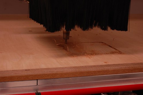
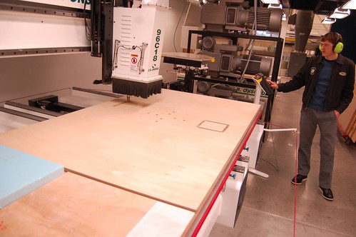
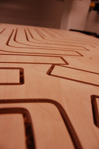
This morning I (and Marc, one of the Fab Lab guys) CNC machined out the parts for my magnet stool in the Digital Fabrication lab here at U of M. It was great, I love the large budget of a huge research university! Lots of cool tech, and lots of it in the Fab Lab!

Being my first time on the machines it took a little bit to set up my file (only 5 hours!) because I had not quite optimized my Rhino file to be machined with MasterCam (the cnc software). But hey, it worked and it's awesome! I'll be sanding and glueing up tomorrow.


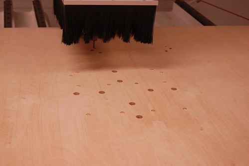
Drilling out some magnet holes.


That's the incredibly helpful Marc. Marc is awesome.


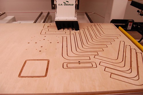
The finished cuts are quite nice, I'll be sanding them with some ridiculously super fine grit sand paper and just regular yellow legal paper (a tip from a friend who worked for Steelcase) for a super smooth and finished edges.

Thanks for reading!

Mobile Kitchen Concepts

In More w/ Less we're working on mobile kitchens as groups currently. They have to fit in a 2'x2'x5' space and cook a full meal. In the words of Jan Henrick (our prof), "I have to be able to cook a meal on them or you fail." So no pressure. Oh and we have 2.5 weeks to make a functioning prototype. Meaning a working kitchen in 2.5 weeks. Again, no pressure.

Our group is trying to make a kitchen that is minimal and portable as possible while still being a useable kitchen. It's exciting!
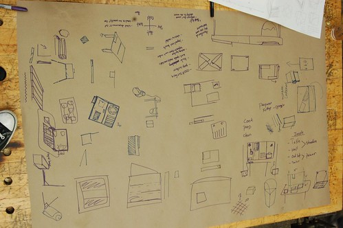
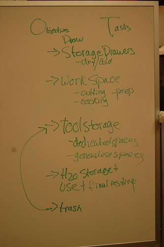
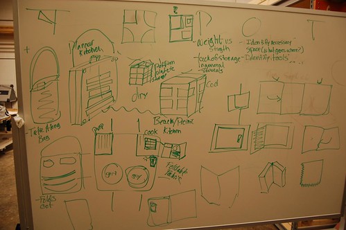
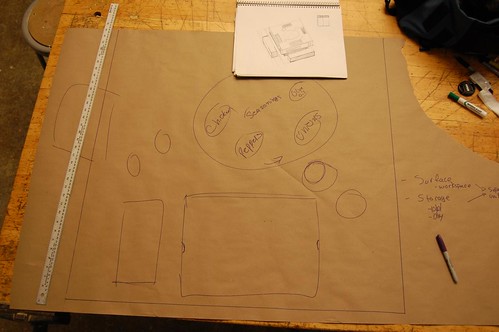
So far, we've filled up a few white boards and large pieces of paper with concepts and sketches.
Below is a few selected images from the concept meetings.


Working out what needs to be in a kitchen.

Drawing kitchen work spaces at full scale to get a stronger idea of scale and usable space.

Thanks for reading!

Monday, October 26, 2009

The Design Zorse

My professor Jan-Henrick came up with this in class last week to demonstrate how some people in the class were falling behind and simply not keeping up with work. Not pictured is the person trampled and bleeding and crying behind the zorse (half horse, half zebra).
A few of us are riding it and taking control, most of us are getting bounced around on the zorses hind legs, and the rest of us are getting dragged along, face in the zorses hind quarters.
And then they're the dead ones crying blood. Yep, Jan is crazy.

Ladies and Gentlemen, The Design Zorse!

"Your thinking, 'this guy is crazy'. Yes. I am." Jan-Henrick Anderson

Thanks for reading!

Sunday, October 25, 2009

Week 4 and the Light Box in Smart Surfaces

Well, it's done.

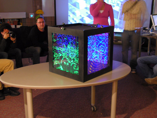
Pretty much, we created a light box that is motion activated when someone walks by. Our group envisioned this project as an installation piece where there would be large scale deployment of these cubes in a large public area (like U of M's Diag). As people move between the cubes in their daily lives the light would follow them through the cubes. Yep, we made an art piece that makes the sun an ancillary part, it's got solar panels on top to charge it during the day.

This was a trying project, and I'm honestly very glad we are done with it. Our team didn't always work well together and I even made the front page of the Smart Surfaces website ranting about it last post. Opps/Nice.

We had Julian Bleecker from the Near Future Laboratory come this week and talk to us about Undisciplinaryism. He commented on each of our projects, but unfortunately seemed to have little to say about our groups projects.

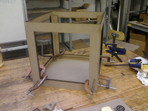
Building the box.


Setting up the wires.


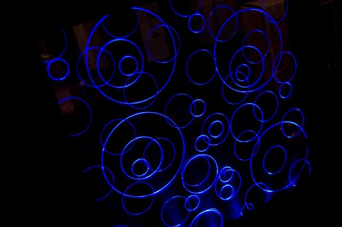
The windows are acyclic that slide down into slots in the box and are then lit by a row of colored LED's from the bottom. Patterns were laser scored into the panes to provide opportunities to light to catch.

(From rootoftwo (John Marhall) on Flickr)

The blue LED's worked very well, and it made the bubbles pane of acrylic look great.

We're onto our final groups and final projects now. I like my group, everyone seems good so far! We presented ideas for our projects today in class and it seemed from all the presentations that the professors (John Marshall, Max Shtein, Karl Daubman) were not extremely excited or happy with our ideas. I'm tempted to ask what they were really hoping for or thinking we might come up. They honestly seemed disappointed. We'll see.

Thanks for reading!

Magnetic Chair (in process)


My magnetic chair is coming along full swing. I've had some hiccups of course, like the bending plywood not bending nearly as tightly as I was lead to believe it would and instead snapping. But over all, I'm ok with the bending ply not working, it was really not a very nice material to look at when layered and the whole reason I wanted to use layered veneers was for the edge quality of layered veneers.
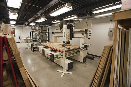
Instead I am CNC machining the legs (well, the entire chair) out of a nice plywood from Fingerlee Lumber here in Ann Arbor (a great local lumberyard, highly recommended). I've got time on the CNC machine tomorrow morning and I'm quite excited, it will be my first time on these machines. I'm so thankful that Michigan has the world class Taubman Architecture college in the same building at the Art & Design school. Because of their huge budget and big money donors (namely the schools name sake, Taubman), they have an impressive amount of tech that I'm able to get my hands on. I love it and kinda wish the Architecture school had a design program as well. Design in the hands of artists is withering out sadly.


The CNC routers. Photo from Julian Bleecker's Flickr.

The other snafu was the magnets I had ordered online turned out to be from a company in Hong Kong. In my haste to order them at the end of a class period, I neglected to check where they were shipping from. So for the chair that I wanted to keep the sourcing local, I end up buying product from Hong Kong. The stupid things aren't even here yet. I ended up buying some neodymium magnets from Stadium Hardware here in Ann Arbor, again highly recommended.
I've worked out where all the magnets lay and will be embedded and I am quite happy with how it should come all together. Below are some screen shots from Rhino of my model and cut files. (I decided not to take the time now and render them nicely, so screen shots it is for now!)

The cut file. I'm cutting 3/4" plywood and sandwiching the pieces to create the size needed. The circles are various drill holes for the friction and magnetic held wooden rods that will hold the chair together while in its 'up' position or the magnet holes for the carrying 'down' mode.

The chair up on the left and the collapsed carrying state on the right. The hole in the back of the seat acts as a handle for carrying the chair.


Another view.

I'll post some process pictures of the CNC and the resulting pieces tomorrow. Thanks for reading!
Related Posts with Thumbnails